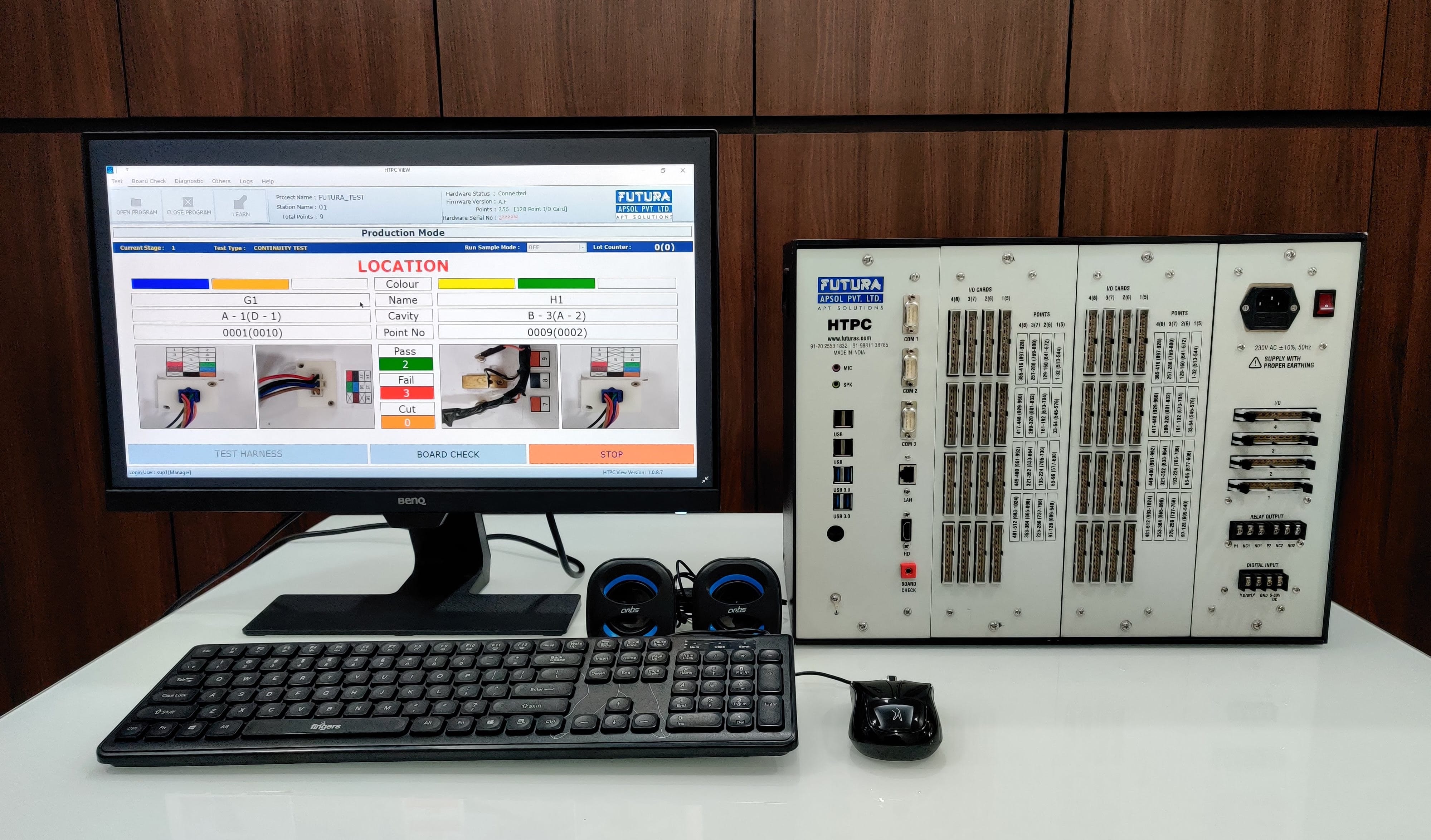
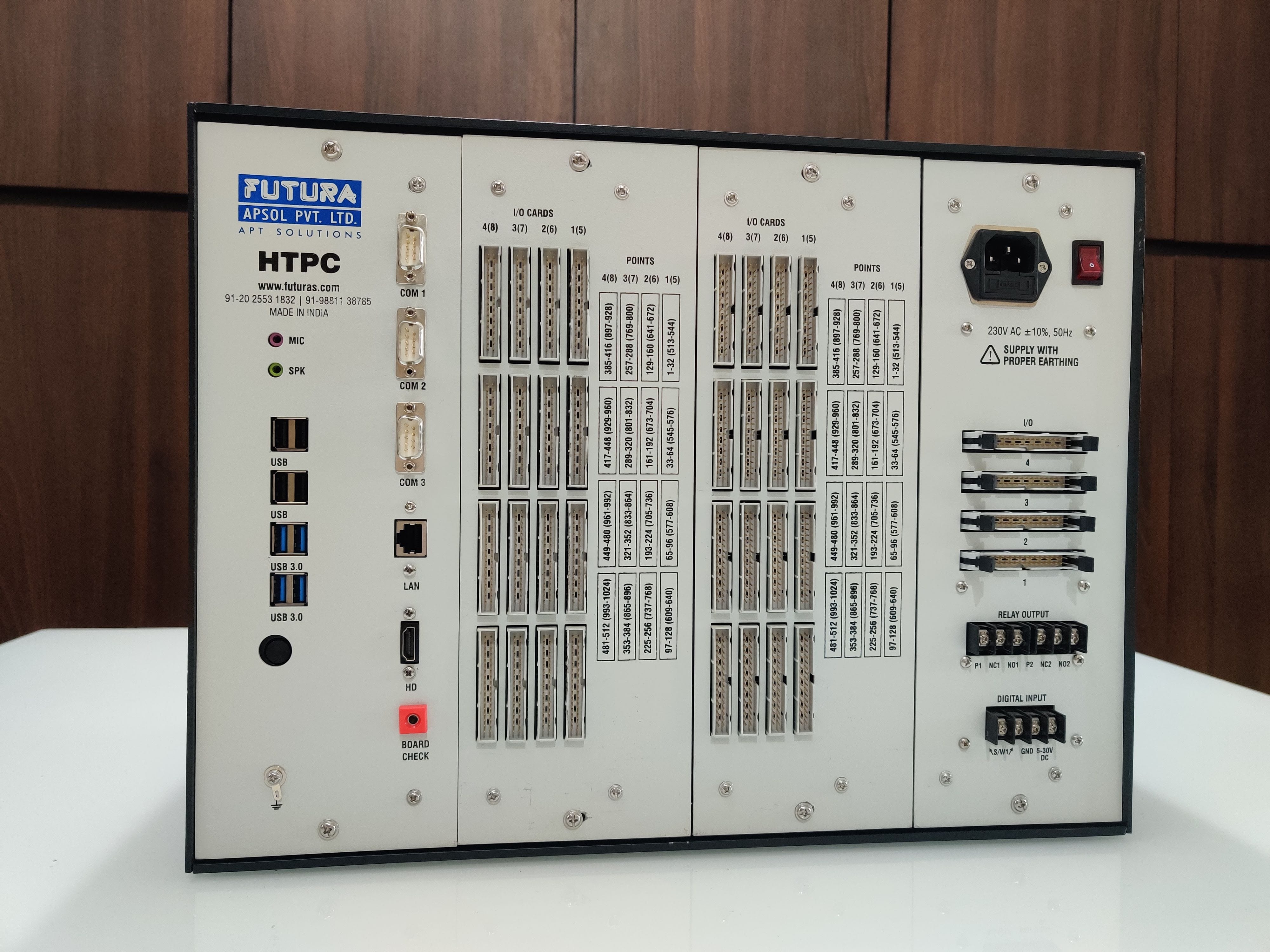
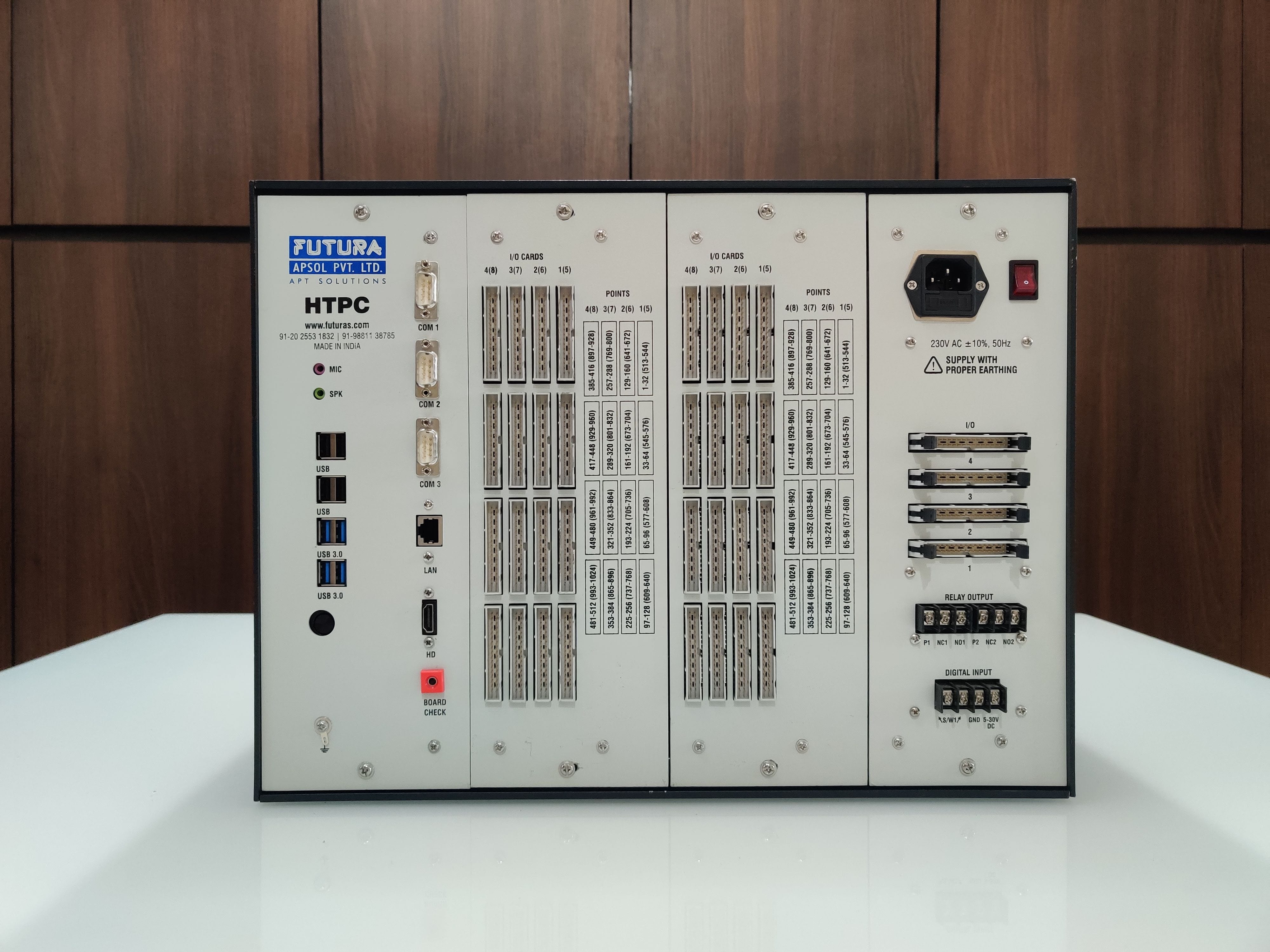
HTPC : PC Based Advanced Harness Tester (128 - 1024 / 128 - 3072 Points)
HTPC is a PC Based, feature-rich wire harness tester offering up to 3072 test points. It also includes GUI based error reporting, data logging and various other features given below.
Features
- Continuity, Diode Checker
- Check Relays in Panel
- Stand-alone system
- Precise testing results
- Digital Input/Output
- User role based access
- Built for rough industrial environments
- Intermittent Checking
Softwares Included
HTPC Editor (Only for Creating / Editing Programs) : Can run on any machine
HTPC View : For Harness Testing
Highlighted Features
GUI Display

Workflow

Sample Harness Checking

Continuity / Diode Checking

Data Logging

Import / Export (Custom Excel File)

Label Printing

LED ON Fixtures

Relay Output (OK Marking / Punch Marking / Auto lock / Unlock / Cutter Module)

Barcode Scanner

Fail Bin / Red Bin Sensor

Label print format is given here
Video Manuals
Program Details
A2. Create / Edit Fixture : Add IO Points and Images
A3. Add New Connections as per Program Manually for Testing
A4. How to add Components (Diodes, etc)
Data Entry / Programming
B1. Export Project / Program CAB File
B2. Import Project / Program from CAB File
B3. Import FCT File by creating New Program
B4. Import HRN File by creating New Program
B8. Self Learnt Data Importing
B9. Program Creation with Fixture Connections and Label File Importing
Calibration
C1. Board Check when Testing is Off
C2. Board Check during Testing
DIAGNOSIS
SYSTEM CHECKING
DATA ENTRY/PROGRAMMING
- Program Creation
- Program Details
- Program Settings
- Learning
TESTING
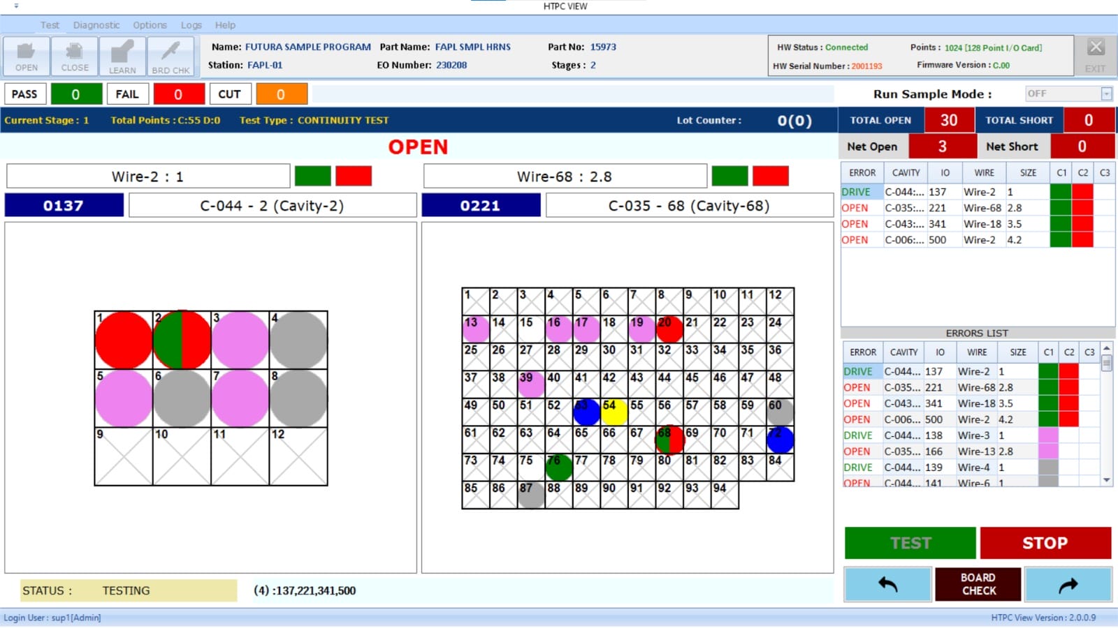
- Continuity (Open, Short, Interchange, Extra Point)
- Diode (directional, polarity, open, short)
- Modes(Production, Sample Harness, Run Sample)
- Multi stage testing
- Testing Methods(Circuit by circuit, all circuit)
- Error Display (Fault Type, IO Point, Fixture Number, Wire Name, Wire Colour, Fixture Image, Cutter Module timer, Sample harness timer)
OUTPUT
- PASS (Label Printing, Audio, Visual, Pass Counter, Relay output/s, Data logging, Signal for Connector Printing)
- FAIL ( Visual, Audio, Fail Bin, External Cutter Module activation signal, Locking, Relay output/s)
DATA LOGGING
- Extensive database logging facility for each cycle
DIGITAL I/O
- Fully customizable
BARCODE PRINTING
- Label Printing
- Barcode scanning for checking correct barcode print
- Barcode scanning for selection of program for testing
- Barcode scanning after harness pass for confirmation of selected program
- Resource Barcode (Confirmation of Child Part Assembly)
SYSTEM CHECKING
- Sample Harness
- Run Sample Mode
CALIBRATION
- Board Check
- Program Check
DIAGNOSTIC
- Self Test
- Internal Memory
- Buzzer
- Real-time Clock
- Serial Port
HTPC | |
---|---|
Test Point Capacity | 128 point to 3072 points |
Expandable in step of | 128 |
Components | Diodes: Checks for proper orientation |
Diode testing | Yes - Diode open: Diode missing or open from inside. Diode short: Diode short from inside or wire assembled instead of diode. |
Test Voltage | Test voltage: 5 V DC. |
Test Current | Test current: In mill Amperes. |
PC | Fan less PC with Windows licensed version. |
Peripherals | Keyboard,Mouse,LCD monitor |
Audible Tones | Settable Pass and Fail tones via speaker |
Serial Ports | Serial port 1: External device communication Serial Port 2: External device communication Serial Port 3: External device communication |
USB Ports | 8 ports (ex Mouse, Keyboard, Barcode Scanner, Label Printer, Pen Drive, etc.) |
Other Ports | 1 HDMI , 1 Audio, 1 Ethernet |
Tester to board connection | 34 Pin Connector to:- Open wire termination.- Centronics termination. (Backward board compatible)- PBT terminations. |
Input Power | Supply Voltage: 230V AC (Input 230V AC +-10%) Power consumption: Approx. 30 Watts. Short circuit protected. |
Size (W x D x H) | 435 mm x 260 mm x 325 mm. (Base unit: For 1024 Point) |
Weight | Approximately 17 Kgs. |
Operating Parameters | Designed for ambient temperature: 0° - 50° C. |
Warranty | Conditional for a period of 12 months |
User Authentication | Login authority manager |
Display Faults | GUI Based Open, Short, Interchange, Extra Point, Diode Reverse, Diode Open, Diode Short. |
No. of Stages Testing | Multiple (Unlimited Stages can be programmed) |
Output on PASS | Relay/s changeover, Visual, Audio, Label Print, External digital outputs, lot/box printing, etc. |
Output on FAIL | Relay/s changeover, Visual, Audio, Fail Bin, External Cutter Module, External digital outputs, etc. |
Barcode Scanning | Yes, multiple options available |
Application | Harness testing for continuity and diode check. |
Program Creation
- Program Creation from HTPC Editor software
- Import from other Futura Tester programs (.HRN / .FCT)
- Self Learnt Data importing
- Import from HTPC exported file
- Import from external files (Excel file, etc)
Program Details
- Program identification (Name, Customer Name, Station name, etc.)
- Fixtures with respective images
- Cavity location in Fixture
- Connections (Wire Name, Wire Colours, Cavity details, IO Point)
- Components
- Digital Input (ex Part detection switches)
- Digital Output (ex Fixture LEDs)
- Label Program Import from previous files (Real time variables)
- Resource Barcodes
- Authority Management
- Multi stage programming settings
- Shift Programming Settings (First Shift Timing, Second Shift Timing, Third Shift Timing)
Program Settings
- Common (Auto Mode, All Circuit Mode, Extra Point, Resource Barcode, Check Barcode, Label Printing, Run Sample Mode)
- Cutter Module (Cut for Open Error, Cut for Short error, Cut for location Interchange Error, Cut for Extra Point Error, Cutter module delay time)
- Sample Harness (Sample Harness delay time, Sample harness step error)
- Capacitor Delay (Starting Delay time, Capacitor Delay time)
- Shift Programming (Targeted Harnesses, Shift Time)
- Clear Count(Clear Pass Count, Clear Fail Count, Clear Cutter Count)
- Stage Circuit (Stage Circuit Action)
- Lot Quantity (Lot Quantity, Lot Counter, Import PRN File)
Testing is done with HTPC View Software.
Continuity Testing
- Open
- Short
- Interchange
- Extra Point
Diode Testing
- Diode directional testing in the wiring harness can be tested.
- Diode to be programmed through software, learning is not available.
- Directional testing is done, i.e. diode polarity can be checked.
- Diode Open, Diode Short error types can be checked.
- Diode missing, Diode shorted from inside, Diode assembled in reverse direction can be identified.
Modes
- Production Mode
- Sample Harness Testing Mode
- Run Sample Mode
Multi Stage Testing
- Multiple stages of harness can be programmed and tested.
- Testing is done stage by stage.
- Each stage can consist of continuity and diode.
- Unlimited stages.
- Data logging according to each stage.
Testing Methods (Settable for each stage seperately)
- Circuit by circuit
- All circuit
Error display
- Fault Type
- IO Point
- Fixture Number (With Cavity)
- Wire Name
- Wire Colour (Multi Colour)
- Fixture Image
- Cutter Module timer
- Sample harness timer
- Cavity Overlay over Fixture Image
- LED Outputs available for Connector mounting guide and Error indication
- Part detection switches for connector insertion detection
Pass
- Visual output
- Label printing with real time user defined data
- Audio output (User selectable)
- Relay output/s
- Pass counter
- Data Logging
- Signal for Connector Printing

Fail
- Audio output (User selectable)
- Visual output (Fault Type, IO Point, Fixture Number (With Cavity), Wire Name, Wire Colour (Multi Colour),Fixture Image, Cutter Module timer, Sample harness timer)
- Relay output/s
- Data Logging
- Cutter Module Activation Signal
- Critical harnesses where rework is not allowed after found faulty are cut using this mode.
- Activation/Deactivation of cutter for each error, is programmable.
- Individual error timing is programmable.
- After mounting harness if error arrives, down counter is started and operator have limited time to correct the error if not harness will be cut.
- Harness cutter can be designed as per user requirement and interfaced with tester
At every pass, fail, cut, sample test, cutter event, stage completion, data is logged.
- Station_Name
- Program_Name
- Testing_Mode
- Result
- Date
- Time
- Pass_Count
- Fail_Count
- Cutter_Count
- Lot_Count
- Operator1Code
- Operator2Code
- Label_Serial_No
- Revision_No
- Shift
- Error_Type
- Error_Point1
- Error_Point2
- Error_Point3
- Error_Point4
- Wire_Details
- Barcode1
- Barcode2
- Barcode3
- Barcode4
- Barcode5
- Barcode6
- Barcode7
- Barcode8
- Barcode9
- Custom_Field
- Cycle_Start_Time
- Cycle_End_Time
- Cycle_Time
- Cycle_Error_Points_Log
Barcode Printing: Label Printing
- Provision for label sticker generation at harness pass is available.
- USB port label printing is available.
- Programming through .prn file import in to the harness program.
- Can be connected to any label printer and programming is through .prn file.
- Variables such as date, time, serial number, shift, barcodes, operator codes, and many more are present in the label and can be customised in the future as per requirement.
Barcode Scanning
Barcode Scanning for checking correct barcode print
- Various barcodes are printed on the label during sticker generation.
- Rechecking these barcodes with respect to correct data is printed or not,
- Proper scanning, proper scanning can be done.
- Generating and checking unique barcode for particular harness can be done.
Barcode scanning for selection of program for testing.
- Program can be selected for testing through barcode scanning.
- Correct program selection and manual selection can be avoided.
- Barcode to be scanned for program selection is programmable.
- USB barcode scanners can be connected.
Barcode Scanning after harness pass for confirmation of selected program
- Manual selection of program can be confirmed after testing through barcode. Programming is available through authority menu.
Resource Barcode (Confirmation of Child Part Assembly)
- Harness is a combination of various raw materials such as cable, sleeves, gromets, plastic tags, wrapping tape and many more.
- These materials can be acquired from various bins at the time of production.
- Each of these bins can have unique barcodes.
- These barcodes can be scanned before production for confirmation purpose for selection of correct material.
- Resource barcodes checked in both sequential and random modes.
DIGITAL I/O
- Fully Customizable Digital Input/output Resources which can be triggered on various events like PUT CABLE, HARNESS PASS, HARNESS FAIL, etc.
- Digital I/O settings can be used to configure various modes depending on the requirement.
Use cases
- Before Starting the Testing cycle, glow LEDs of Fixtures where connector is to be inserted
- Glow Error Fixture LEDS on during Testing
- Detection of Connector removed from fixture during harness testing
- Glow specific inputs after a certain stage is passed / failed
- Wait for input from external sources at user customizable given event
Events
- PUT CABLE
- HARNESS PASS
- HARNESS FAIL
- START TESTING
- ERROR
Action
- SPECIFIED PIN INPUT / OUTPUT -> ON / OFF for Duration
Workflow
Events
- Open Error
- Short Error
- 2 Point Interchange
- 4 Point Interchange
- Stage Pass
- Stage Fail
Actions
- Operator Guide
- Label Print
- System Lock
- Restart Testing from First Stage
- Restart Testing from Current Stage
Sample Harness
- Used for daily set up or calibration activity.
- Faulty sample harnesses with different pre-determined errors such as OPEN, SHORT, LOCATION and EXTRA with defined points can be tested.
- Unlimited number of steps can be programmed.
- Each step is user programmable with time counter as per user need.
- Each step needs to be completed, for example if Step is OPEN Error i.e., OPEN 0002 and 0032
- Then after mounting faulty harness with OPEN 0002 and 0032 error, only, this step is passed.
- Data logging after each step is completed.
- If terminated in between or misused by operator or bypassed then tester will be locked and at next power on SUPERVISOR intervention it will be unlocked.
- Pass and fail count will not be incremented and no label is printed in sample mode.
Run Sample Mode
- During production mode running, if any sample is to be tested randomly for cross verification this mode is used.
- Harness PASS/FAIL declaration.
- No label print if harness pass.
- No relay is activated for PASS/FAIL.
- Counters such as pass, fail, cut, serial number, are not incremented.
- Data is logged at this event.
- As the tester compares data or connections of a standard harness with the connections of Harness under Test; calibration is not required.
- HTPC does not measure any absolute quantity hence calibration is not required.
- To confirm functionality of the test system i.e. test equipment along with test rig, following procedure can be repeated after fixed period say 3 months or 6 months.
- Sample Harness testing facility for Master Sample.
- To check functionality of the equipment and the board, “check board” facility
Board Check
- Board check facility available through board check probe for board and IO diagnostics.
Diagnostic
- Self Test
- Self-test for IO points and cards is available.
- Internal Memory
- Buzzer
- Real-time clock
- Serial Port
CAB File (Individual Program File)
- Import / Export from Project File (.CAB)
Import Program from CAD Generated Excel File
- Import Program from multiple types of Excel (.xslx) Files
Export Program to CSV / Excel
- Export Program to CSV File
- Export Program to Excel File(.xslx)
- Total Number of points
- Screen size : 18 inch
asd