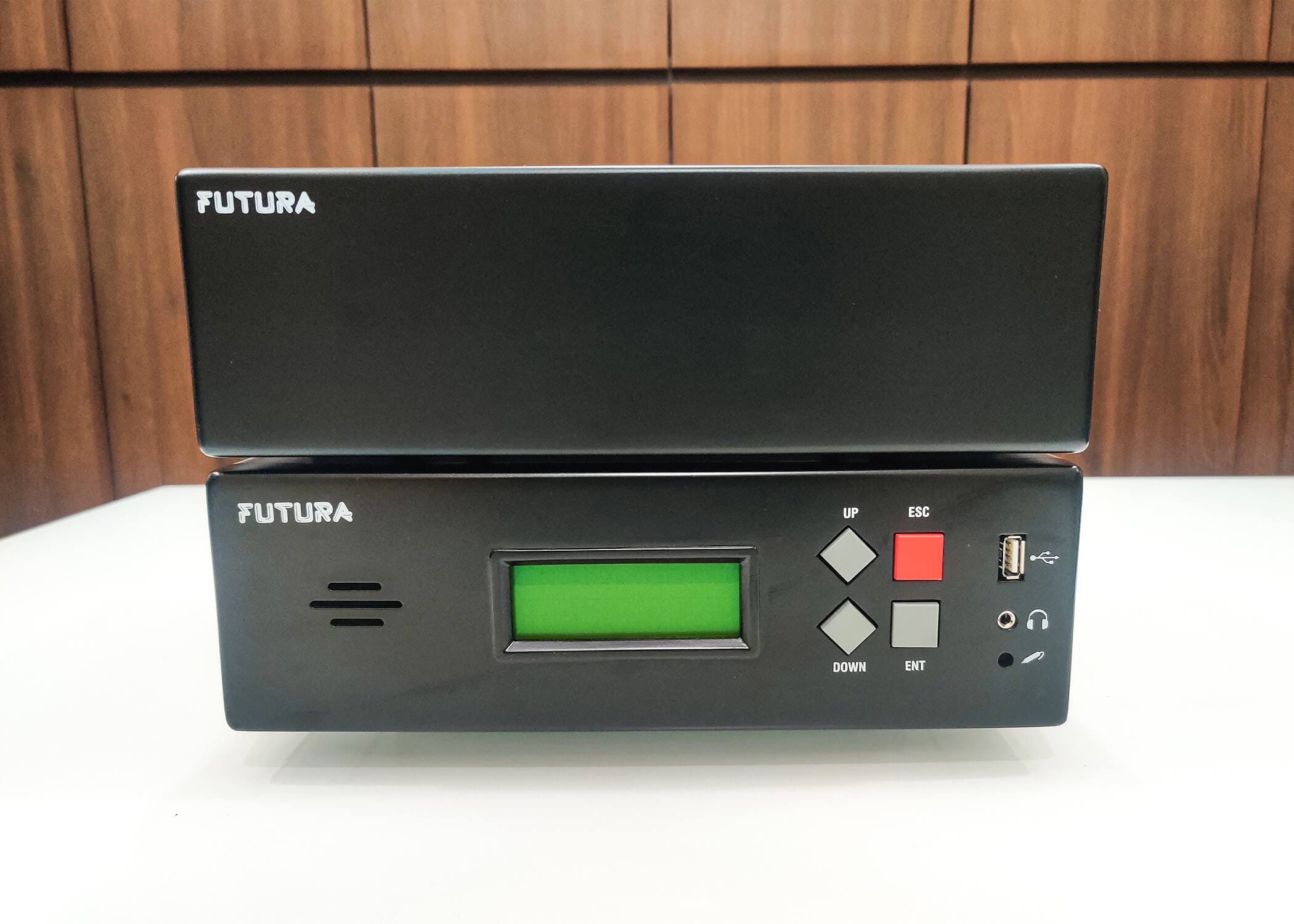
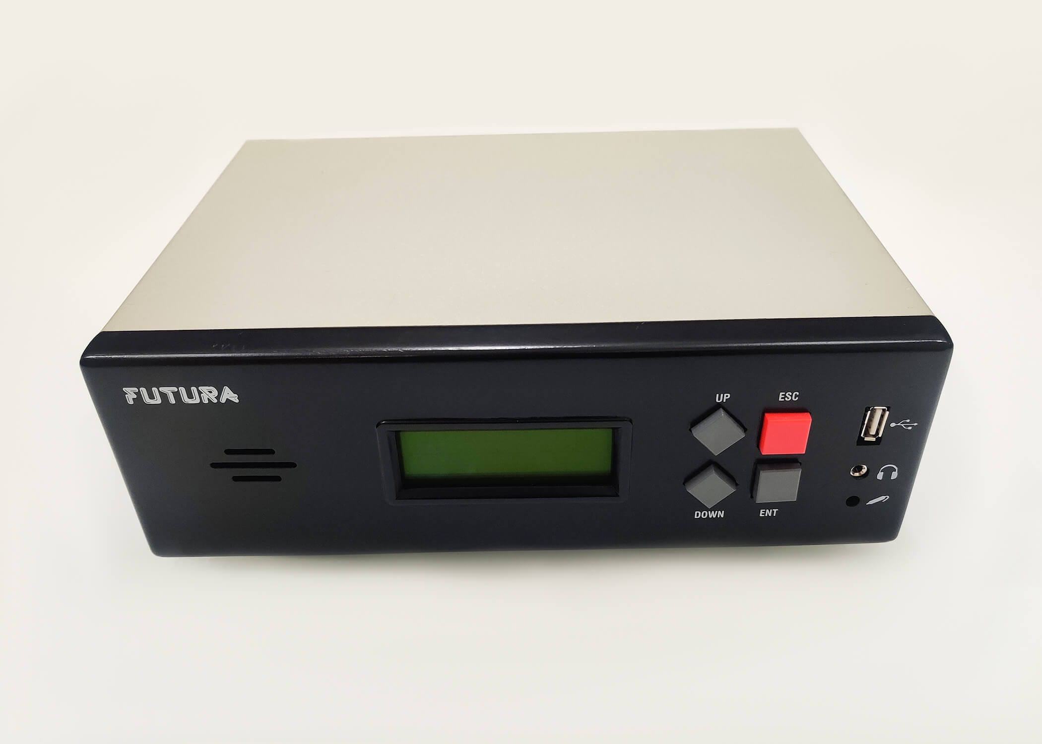
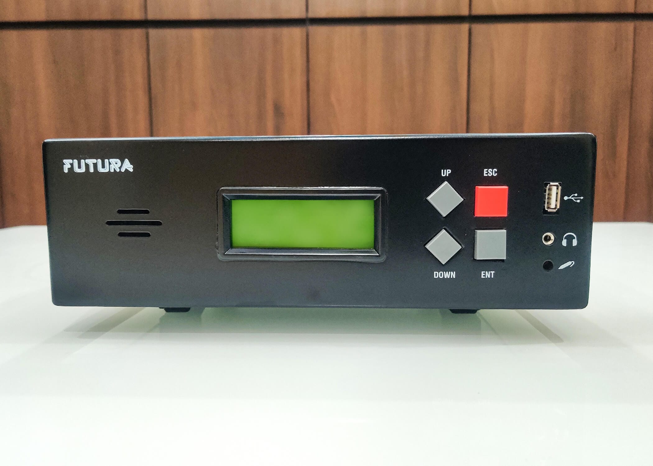
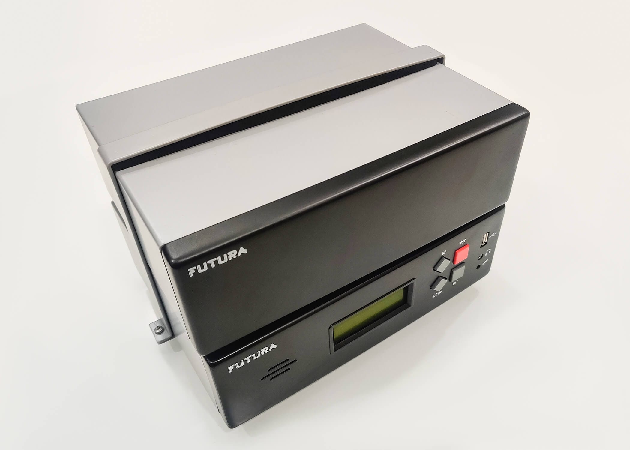
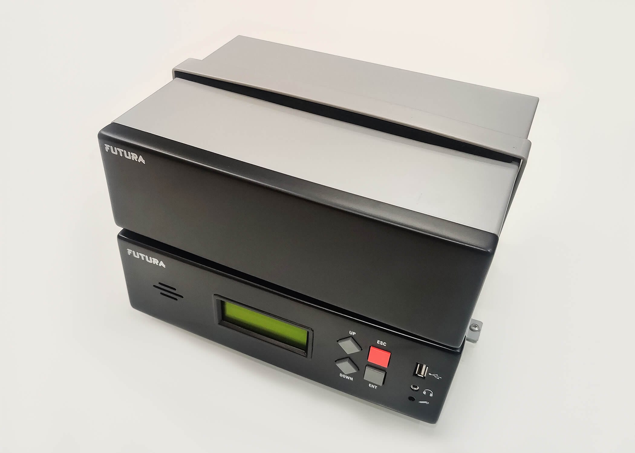
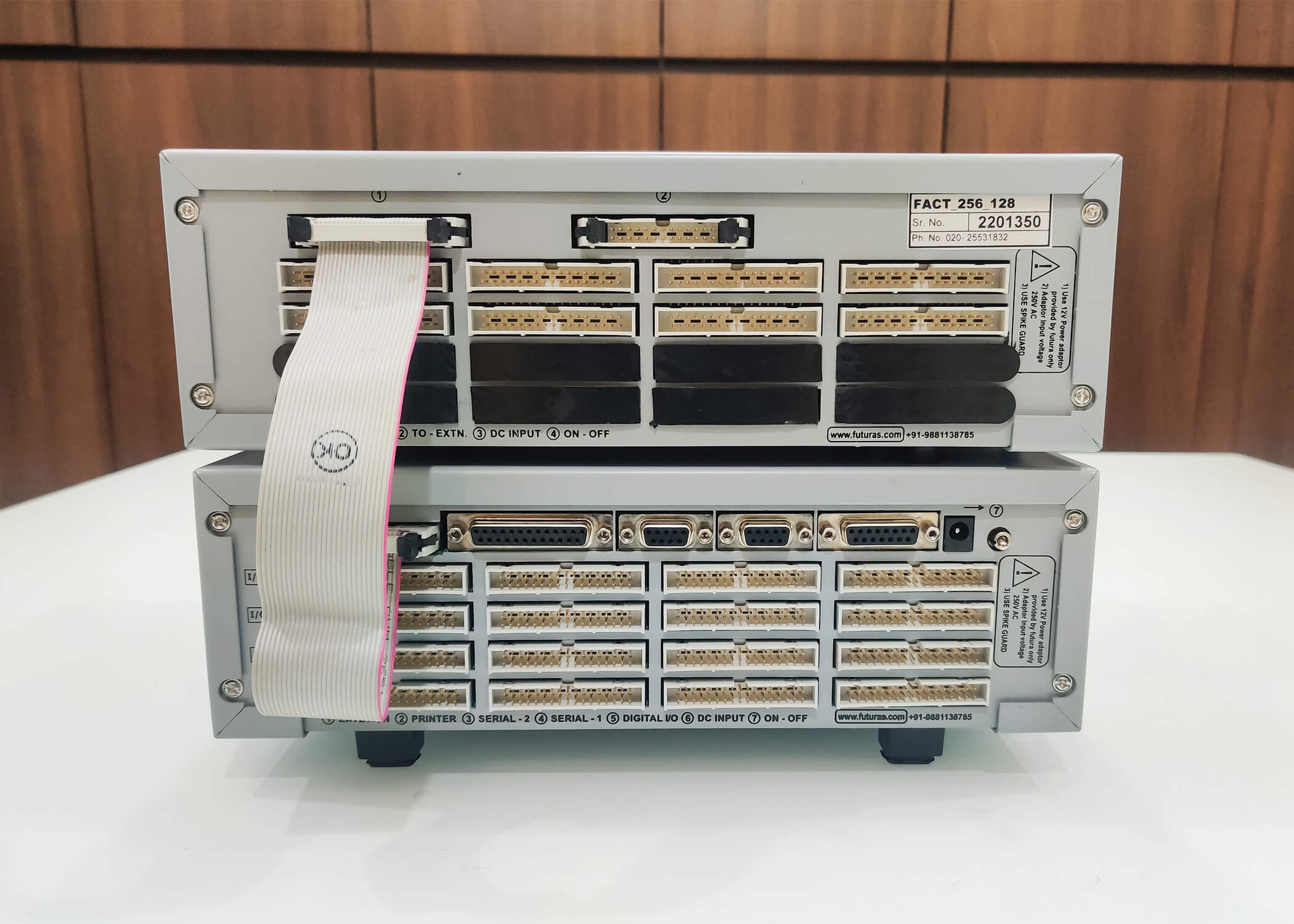
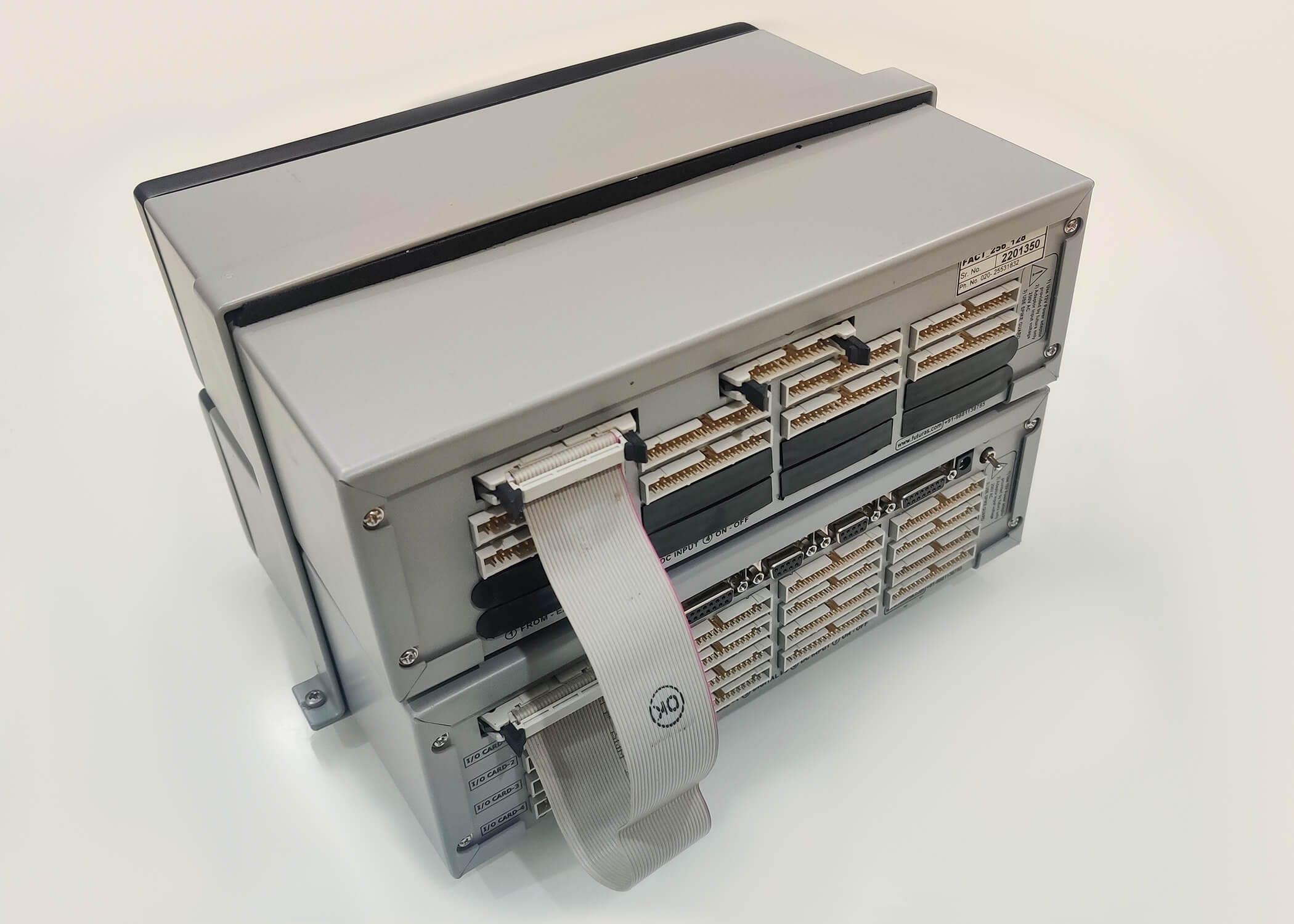
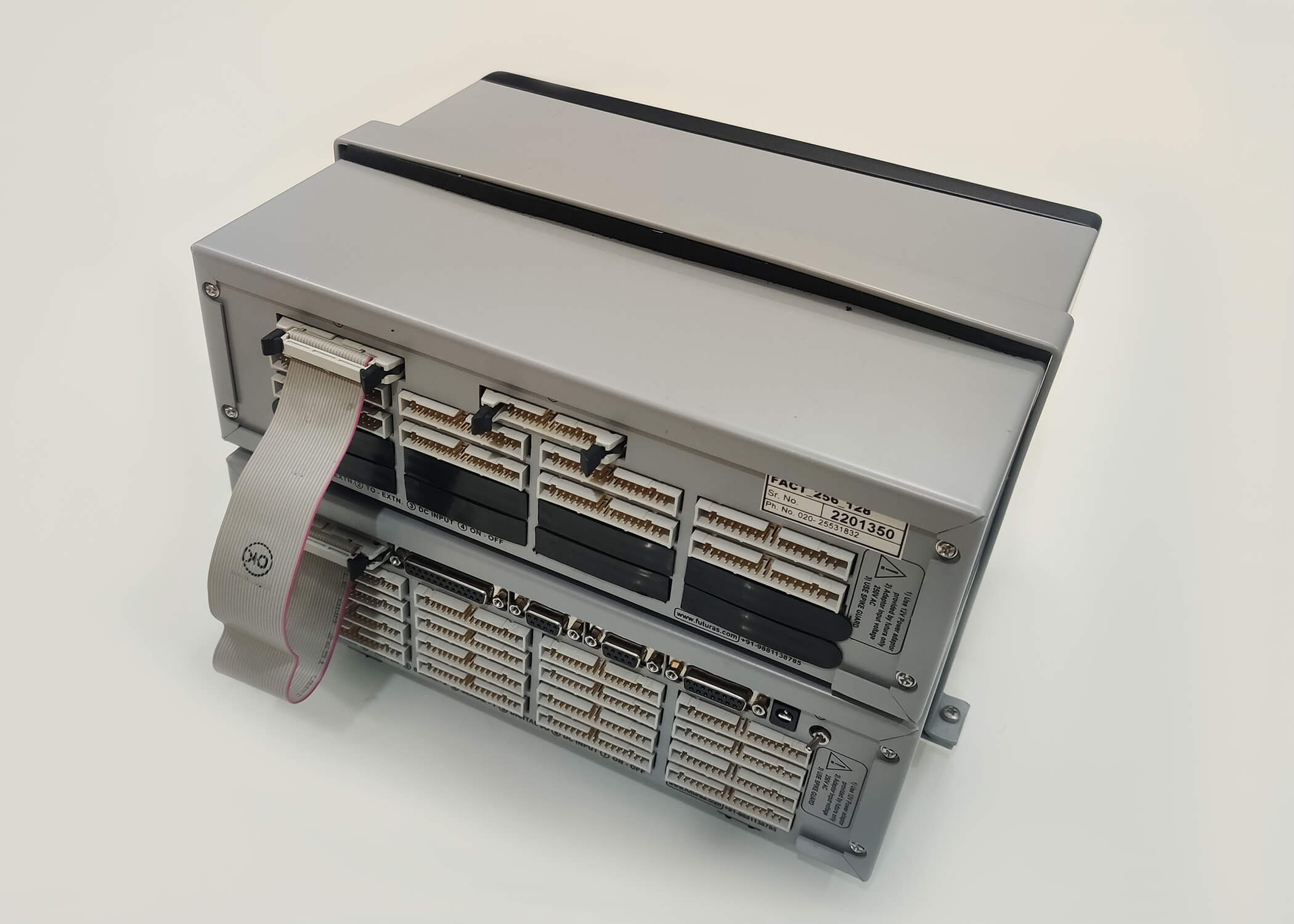
FACT : Wire Harness Advanced Tester (64 - 512 / 128 - 1024 Points)
Economical, feature-rich, stand-alone Wiring Harness Tester
Futura's Advanced Continuity Tester is an economical, feature-rich, stand-alone Wiring Harness Tester offering up to 1024 test points. The powerful FACT Editor software application is used to create unique program files to successfully validate all electrical and electro-mechanical wire harness parameters.
Expandable PointsContinuityDiode CheckingRole based login via USB
Other Features
- Label Printing
- Barcode Scanner
- Pass, Fail Relay Output
- Fail-bin Sensor
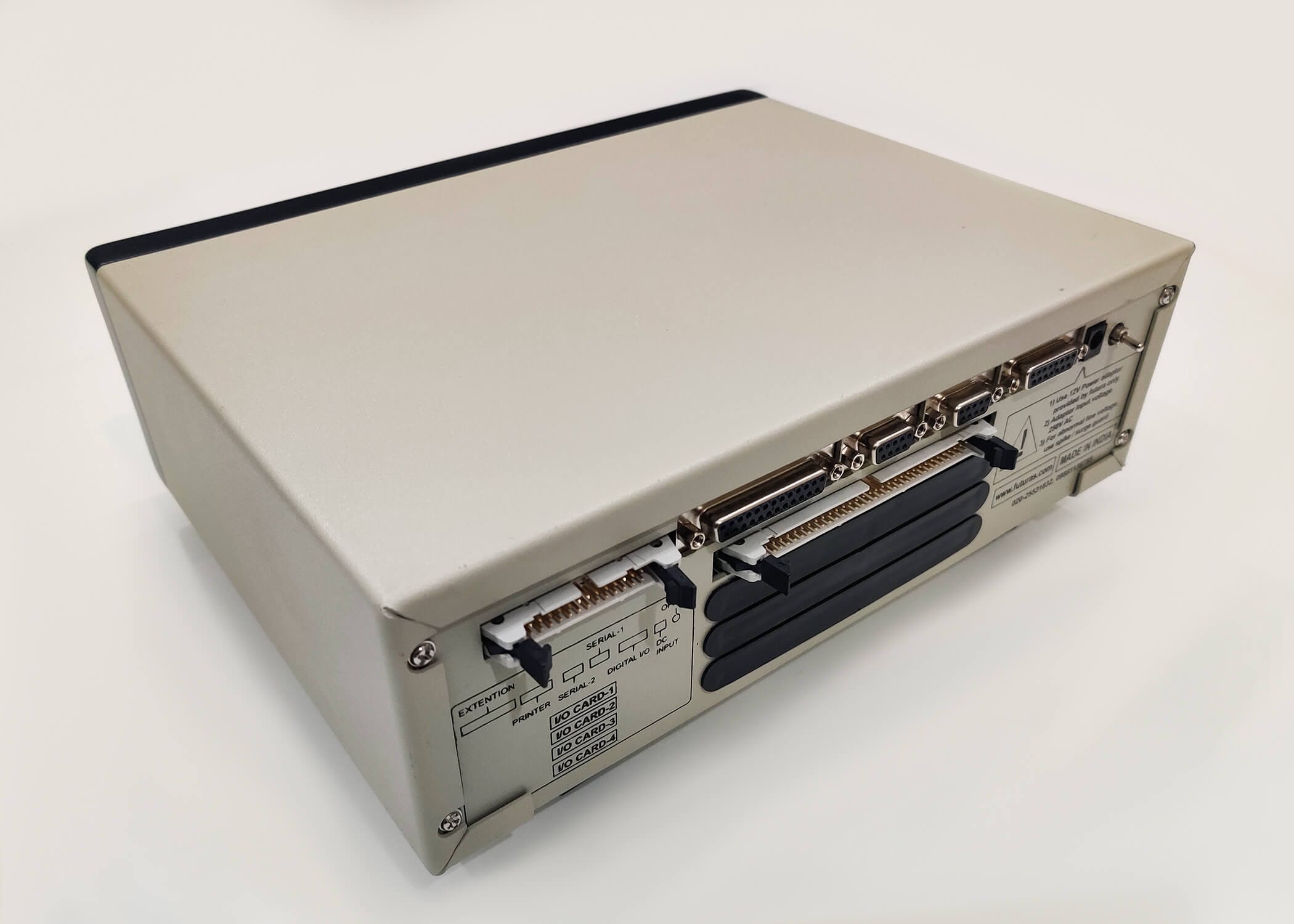
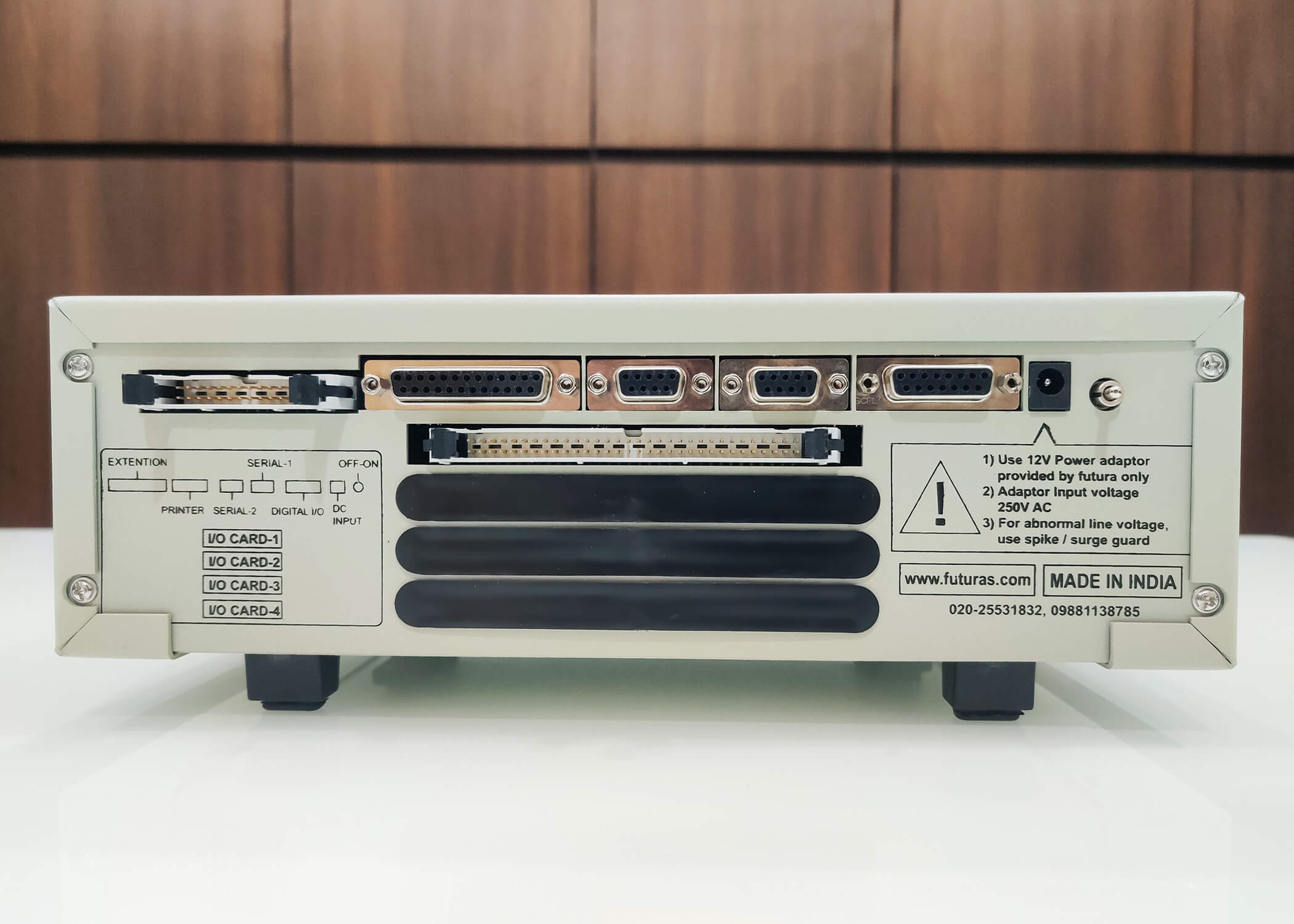
TEST POINTS: 64 - 512 / 128 - 1024 POINTS

DATA ENTRY/PROGRAMMING
- Program Creation
- Program Settings
- Learning
TESTING
- Continuity (Open, Short, Interchange, Extra Point)
- Diode (directional, polarity, open, short)
- Modes(Production, Sample Harness, Run Sample)
- Two stage testing
- Testing Methods(Circuit by circuit, all circuit)
- Error Display (Fault Type, IO Point, Fixture Number, Wire Name, Wire Colour, Fixture Image, Cutter Module timer, Sample harness timer)
OUTPUT
- PASS (Label Printing, Audio, Visual, Pass Counter, Relay output/s, Data logging, Signal for Connector Printing)
- FAIL ( Visual, Audio, Fail Bin, External Cutter Module activation signal, Locking, Relay output/s)
DATA LOGGING
- Basic data is logged in USB Storage for each PASS/FAIL event
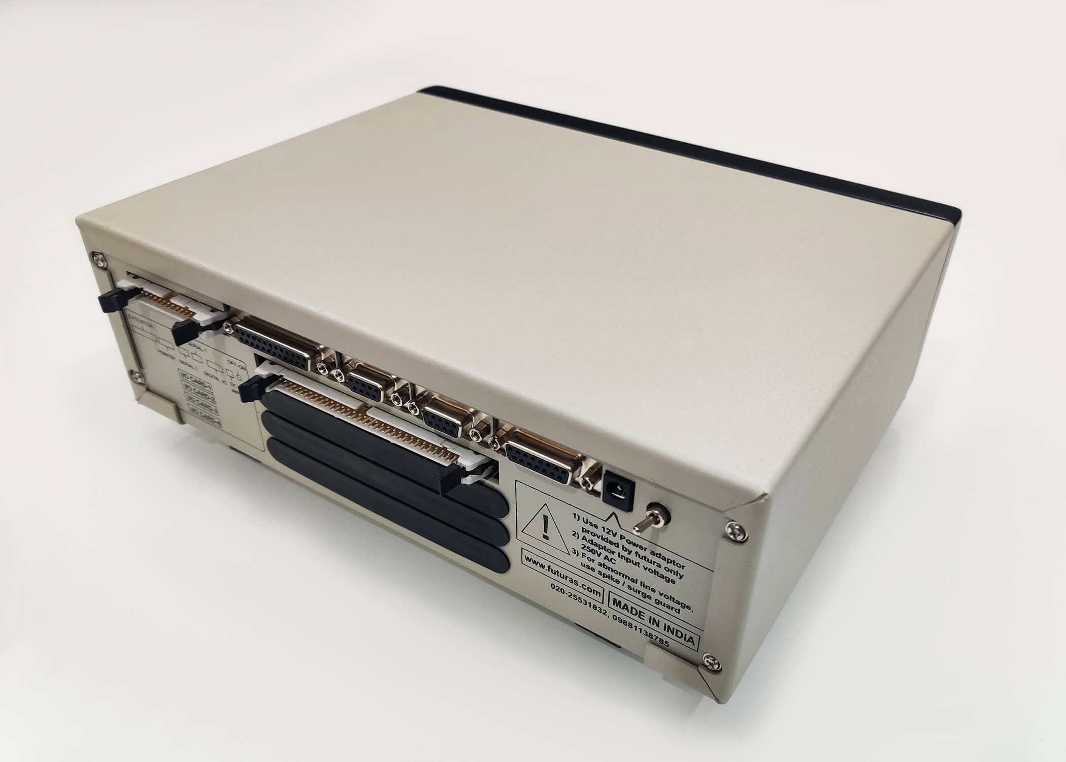
DIGITAL I/O
- HACG as external accessory
BARCODE PRINTING
- Label Printing
- Barcode scanning for checking correct barcode print
- Barcode scanning for selection of program for testing
- Barcode scanning after harness pass for confirmation of selected program
- Resource Barcode (Confirmation of Child Part Assembly)
SYSTEM CHECKING
- Sample Harness
- Run Sample Mode
CALIBRATION
- Board Check
- Program Check
DIAGNOSTIC
- Self Test
- Internal Memory
- Buzzer
- Real-time Clock
- Serial Port