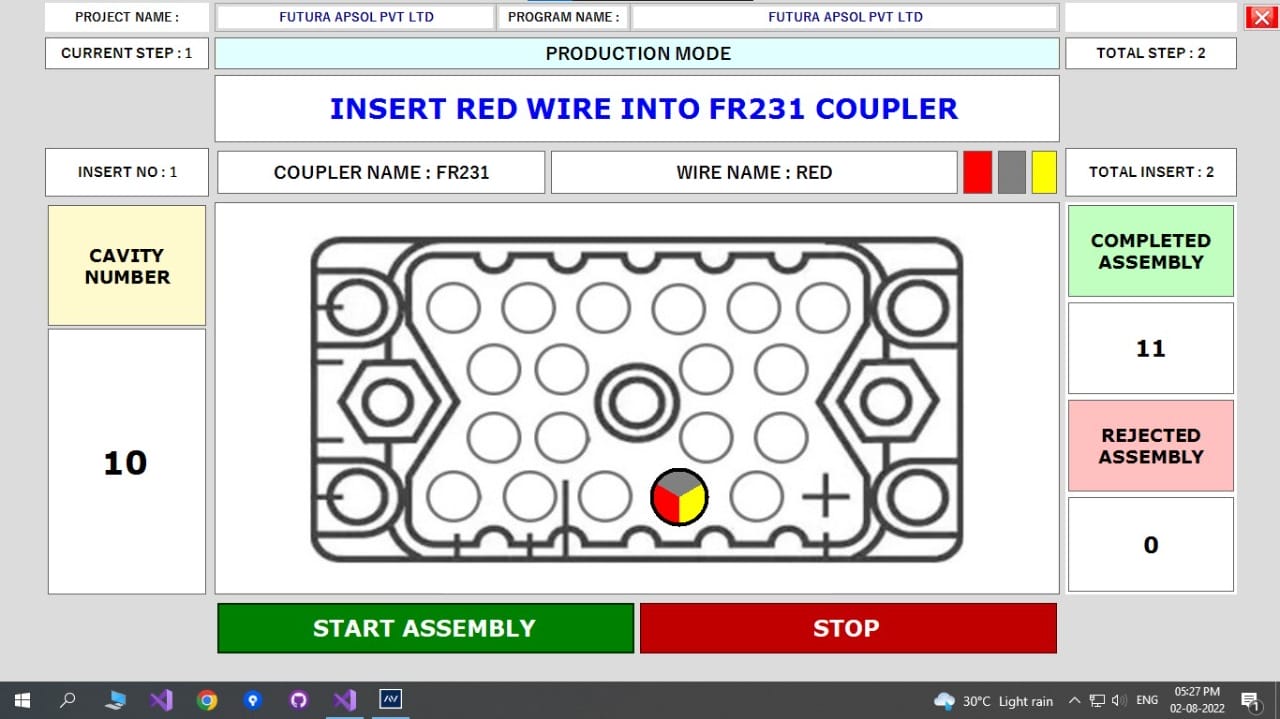
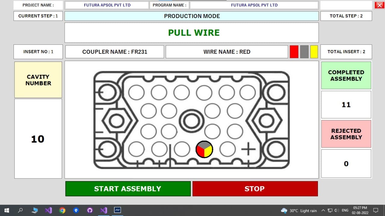
NAVPC : PC Based Harness Assembly Aid / Common Point Guide / Navigation
NAVPC is a PC Based, feature-rich wire Harness Assembly Aid / Common Point Guide / Navigation System
Features
- Stand-alone system
- De-skill Harness Assembly Process
- User role based access
- Built for rough industrial environments
- Checks for correct continuity, insertion location, and terminal backout TBO
- Several Modes for different operations
The complete system is :
- Test blocks / fixtures with I/O points (for continuity), LED indication (I/O LEDs) under each cavity to indicate where to insert. Test block also has a switch which operates on pulling a locked cable.
- Treys with LEDs on each trey to indicate from where to pick up a cable.
- HAAP1208 slave unit connected to trey LEDs, I/O LEDs, I/O Points and switch indicating pull.
Installation:
- Wiring
- Program Creation
Highlighted Features
GUI Display

Continuity Checking during assembly

TBO (Terminal Backout) Detection

De-skill process Harness Assembly (Insertion) Process
NAVPC | |
---|---|
Test Point Capacity | 128 and above |
Expandable in step of | 128 |
Components | not applicable |
Diode testing | not applicable |
Test Voltage | Test voltage: 5 V DC. |
Test Current | Test current: In mill Amperes. |
Test Speed | 1 seconds per stage |
Display | Monitor |
Audible Tones | Piezo Buzzer on pass, fail with tone and volume control |
Number of Harness Programs | 128 |
Serial Ports | PC: Standard 1 RS232 serial port. |
Printer Port | 9 pin D for serial port printer |
Test Point Interface | Output of I/O consist of 34 pin FRC connector which can be interfaced with pcb then can be connected with 2 pin relimate. |
Input Power | Supply Voltage: 12 V DC, 2A. (Input 230V AC +-10%) Power consumption: Mili-Watts. Short circuit protected. |
Size (W x D x H) | Master: 165 X 80 X 60 mm , Slave: 140 X 80 X 35mm |
Weight | Approximately 5 Kgs. |
Operating Parameters | Working temperature: 0 - 50 C. |
Warranty | Conditional for a period of 12 months only for new equipment/products |
User Authentication | USB Pendrive (Soft Key) |
Display Faults | open |
No. of Stages Testing | 1 stage |
Relay out Put | Potential free Relay outputs 2 numbers, up to 230V AC, 5A load. 1 is configured as pass relay and relay 2 is configured as fail relay. |
Barcode Scanning | Yes |
Application | Guides in making harness assembly, checks correct locking of terminal, by pulling inserted terminal and also checks continuity. |
Program Creation
- Program Creation from NAVPC
- Program Creation from HAAP Editor
- Import from other Futura HAAP / NAVPC programs
Program Details
- Program identification (Name, Customer Name, Station name, etc.)
- Fixtures
- Cavity Location on Coupler
- Connections (Wire Name, Wire Colours, Cavity details, IO Point)
- Label Program Import from previous files (Real time variables)
- Resource Barcodes
- Authority Management
- Multiple Coupler Insertion Detection
Assembly Display
- Indication for correct selection of wire
- Indication for correct insertion location/cavity.
- Terminal backout checking with appropriate fixture
- Checking continuity of circuit (Open, short, interchange)
Details shown
- Fault Type
- IO Point
- Fixture Number (With Cavity)
- Wire Name
- Wire Colour
Assembly Pass
- Visual output on Monitor
- Label printing(with real time user defined data)
- Audio output
- Relay output/s
- Pass counter
Assembly Fail
- Audio output, Visual output (Fault Type, IO Point, Fixture Number (With Cavity), Wire Name, Wire Colour)